Electromagnetic Interference in Hearing Aid T-Coil Applicationsby Barry McKinnonNorth Vancouver, BC V7M 1R9 Originally presented at the 1994 CAA Conference in Ottawa 0 INTRODUCTIONOur firm was retained to investigate complaints of high levels of electrical interference experienced by University of British Columbia staff wearing hearing aids in the newly constructed Brock Hall. The architect requested that we try to identify the source of the noise and see if it may be related to a deficiency in the construction of the new facility. The noise was affecting staff members using the T-Coil setting on hearing aids. The T-coil is a coil of wire that is switched in place of the hearing aid microphone to allow the hearing aid to pickup the varying magnetic field at the earpiece of a telephone handset. It is essentially one half of a transformer, the other half being provided by the handset or an induction loop in a listening assistance system. We often specify listening assistance systems in our sound system design work for theatres and other public spaces, and we are familiar with a number of typical causes of electromagnetic interference (EMI) in this application. We expected that the noise was being caused by devices such as "Power Smart" type fluorescent ballasts and other conventional electrical noise sources such as transformers and motors. We reviewed a set of electrical drawings to attempt to identify the most likely noise sources, and then arranged to meet with Ruth Warick, the Director of the Disability Resource Centre, located in the new building, and have the noisy areas located for us. Ms. Warick regularly uses a hearing aid equipped with a T-coil in her office where, ironically, the noise was reported to be the worst. 1 TESTING PROCEDURE
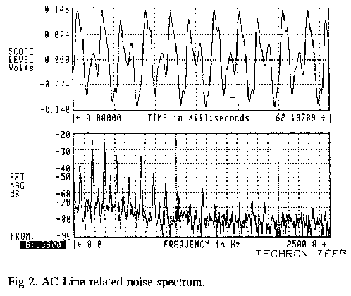
The unit also has an audio output jack to allow monitoring of the signal being received at the meter. We do not have sufficiently accurate information on the frequency response uniformity or bandwidth limits of this audio output to know that what is heard or recorded on this output is an accurate representation of source spectrum. We used a portable Digital Audio Tape recorder to capture the signals from this output for later FFT analysis. The audio output was also used to feed a small powered "Walkman" type loudspeaker so that several people in attendance might hear the EMI effects. We found that it was extremely unpleasant to wear ear-bud type earphones or headphones while using the FSM, since the onset and level of noise could be quite extreme, presenting an indication of the effect on hearing aid wearers. We carried the Field Strength Meter (FSM) through the area at ear level to determine what the EMI levels were in relation to the signal that was intended to be received (the telephone). 2 THE NOISE SOURCESThe most likely noise source, the fluorescent ballasts, were quickly eliminated as the cause of the noise. It was necessary to get within 300mm of the fixtures before a single LED would light, corresponding to a level of -31dB A/m. The noisiest area was in the immediate vicinity of the Director's office and the adjacent small conference room. The conference room was equipped with a VCR and a 28" TV monitor, which when powered up, produced a very broadband noise spectrum typical of the square waves produced in the switching power supplies of modern TV monitors. The FFT spectrum is shown below in Figure #1. The field was quite uniform around the monitor, and the receive level was very dependent upon the orientation of pickup coil. Those people with hearing aids could find a head orientation that would minimize the pickup level, but the field strength was as high as 5 LEDs within 1500mm of the monitor. The PC type computer in Ruth Warick's office produced a similar spectrum of noise. The CRT monitor was responsible for a significant portion of the noise, but the CPU was contributing a continual background "hash" of noise as well. This was measured in excess of 5 LEDs at the operational distance of arm's length to the computer keyboard. Over and above these two specific broadband noise sources, there was a sharply localized hum that was definitely related to the AC line frequency. We tracked the highest signal strength to a line at floor level that made a ninety degree bend in the corner of the office, and a second ninety degree bend just outside the office, along the wall of the conference room. Reviewing the electrical drawings once again did not present any likely culprits for electrical noise in this location. We went into the basement of the building to look for the electrical service that may be causing the EMI. The main AC service entry to the building was in a location considerably removed from the Director's office. It did correspond to the location of a complaint of EMI in a seminar room in the basement. The three phase 600 Amp service to the building was a significant source of EMI across one corner of the seminar room. The noise there was noticeably different in harmonic content from the noise encountered in the Director's office, having a much stronger fundamental. The underside of the slab was accessible throughout the area where the EMI was tracked, as the basement was undeveloped. The building heating services entered directly under the Director's office, tight to the underside of the slab. There was a steam pipe and a hot and cold water return following the path, but no electrical service evident. We were informed that there was no in-slab electrical in the building, which left only the pipes. When we measured up tight to the pipe wrap insulation we found that the pipes were definitely the source of the EMI. The FSM went off scale within 25mm of the pipe insulation on the steam pipe which seemed to carry the highest current. Calculating backwards from the FSM indicators (which are only bandwidth rated for 300Hz-3300Hz) the current in the pipe was in the order of 1 Ampere in the FSM bandwidth. The FFT display in Figure #2 shows the 60Hz AC line frequency fundamental some 15dB below the 300Hz harmonic which falls within the FSM bandwidth. The noise spectrum suggests the sum of ground currents from a variety of devices and phases, producing high harmonic content.
3 ATTEMPTED REMEDIESSince the pipes passed through a mechanical room immediately adjacent to a large distribution transformer, we thought that there may be some induction into the pipes which formed a huge loop back to the University's Physical plant. Attempts to ground the pipes at the mechanical room actually increased the field strength, indicating that the current flow was from outside the building to the lower impedance ground point. Attempts to ground the pipe at the service entry point decreased the field strength along the pipe by approximately 4dB, but increased the field strength in the immediate vicinity of the Director's office. The building ground in this new facility was likely superior to the buildings nearby that were connected together through the steam and water pipes. We were measuring ground current from other buildings flowing to the electrical ground for Brock Hall. The ideal solution would have been to install flexible, non-conductive isolators in the lines which would have provided the required break in the ground path. This was not possible at this stage of the building construction. The mitigating solution chosen by the contractor was a ground at the building entry, which did, at least, improve the condition for the largest number of people. The measures taken to alleviate the EMI were limited to those that were non-invasive to the building structure. There was no opportunity to try magnetic shielding above the piping carrying the current. Because the currents on the pipes were not extremely high, there was no concern for increased corrosion, so there was no secondary justification for having non-conductive isolators installed in the pipes to break the current flow. The problem encountered in the basement seminar room was countered by using an FM listening assistance system. There was no practical approach to shielding the room from the magnetic field produced by the AC service to the building. We suggested that UBC's Engineering Faculty may want to make this a student project, and investigate other avenues, such as active cancellation of the magnetic field. 4 SCOPE OF THE PROBLEMThe EMI problems in the new portion of Brock Hall led to a similar investigation in the older section of the building. The problem areas that were identified there were primarily a result of fluorescent lamp ballasts in need of replacement. The Disability Resource Centre pursued this investigation further and found that most buildings on the campus exhibited EMI in some locations, and in varying degrees of severity. The EMI problem is quite different for this T-coil application than it would be for conventional audio system applications. EMI is usually a problem that can be alleviated by ensuring that the system has a carefully conceived and implemented approach to grounding and shielding, and to ensure that signal levels and transmission impedances are suitable for the environment. The T-coil in the hearing aid is specifically intended to pickup a varying magnetic field and translate that to a signal. It is, by design, very vulnerable to the type of noise encountered here. 5 IMPLICATIONS OF THE PROBLEMThe increased awareness of access requirements for those people with a hearing impairment has led to a number of changes in building design criteria. Where access has been identified as a factor, the permissible background noise and reverberation time in rooms have been lowered to accommodate moderately hearing impaired persons. The extent of the EMI problem that was identified here has helped make us aware of another aspect of the problem that was not previously apparent. The EMI factor should have some broad implications for accommodating hearing impaired access in new buildings. The location of major electrical service entry, and major electrical rooms and transformers should not be close to areas where people will be required to use telephones, or the T-coil setting for use with an induction loop listening assist system. This is applicable to conventional building design, as well as large public spaces such as churches and theatres. This may affect the location of pay phones, offices, seminar rooms, and especially audiology clinics. The problems encountered with TV and computer monitors, and computer CPU's may affect the choice and location of this type of electronic hardware. Flat screen LCD panels should have substantially less EMI than the CRT type, and may be a better choice in offices where the use of a T-coil hearing aid is required. TV monitors will always be a problem, as the CRT will be with us for quite some time before flat screen technology becomes affordable. Unusual or unexpected sources of EMI such as steam pipes are hard to consider as problems at the design stage of a building. The important information to take away from the steam pipe scenario is that it takes very little current flow to produce a magnetic field large enough to cause serious interference for a hearing aid wearer. For adequate speech intelligibility, English speaking people with normal hearing require a signal to noise ratio of up to 25dB. There are occasions where we can salvage understanding with as little as -6dB of S/N, but we are more comfortable with higher S/N ratios. In the case of the EMI outlined here we had a S/N of 0dB in most cases, a difficult situation for a phone conversation. 6 CONCLUSIONThe design process is one of constant refinement as we learn of more parameters that affect the final outcome. In the case of disability access, we are continually finding impediments to access that we have been quite unaware of. A chance situation which combined an unusual source of EMI with the worst case scenario of location, and the people affected, has provided us with an opportunity to become aware of new parameters to consider in the design of a building to ensure that it is a safe, functional, and comfortable space to work or live in.
|